

Service \ Scale-up manufacturing \ Cleanroom injection molding
CLEANROOM INJECTION MOLDING
Precision and micro injection molding of medical device components and microfluidic chips in an ISO 7 cleanroom.
MATERIAL
COC · COP · PC · PMMA · PS · PP and more
MINIMUM ORDER
500 units
LEAD TIME
DFM in 1 week · T1 samples in 8–10 weeks
\ OVERVIEW
Cleanroom injection molding
Our injection molding for medical devices, diagnostics and microfluidics runs in a cleanroom that is ISO 7 / Class 10,000 throughout, with localized ISO 6, under an ISO 13485 quality system. The facility produces regulated product at millions of units per quarter. Two kinds of work share the same cleanroom. Precision medical molding covers housings, cartridges, surgical components and consumables. Micro molding replicates sub-200 µm microfluidic channels and arrays, down to 2 µm, from molds we fabricate ourselves.


2 µm
finest moldable feature

±0.025 mm
standard dimensional tolerance

ISO 7
Class 10,000 cleanroom · localized ISO 6

6–8 weeks
tooling to first trial · one all-inclusive quotation

ISO 13485
certified · FDA registered
\ CAPABILITIES
Capabilities and technical specifications
The mold is made here — CNC to 20 µm, MEMS molds to 2 µm — with tooling to first trial in six to eight weeks and one all-inclusive quotation covering DFM, tooling, every trial round, OQ and PQ. ISO 7 across the molding floor, localized ISO 6 where needed, under ISO 13485.
Precision medical molding vs. micro molding
The two differ in feature size, tooling route, qualification requirement and metrology. Both run in the same cleanroom under the same quality system.
ASPECT
PRECISION MEDICAL MOLDING
MICRO MOLDING
Feature size
Above 200 µm — housings, cartridges, surgical components, consumables
Sub-200 µm microfluidic channels and arrays
Selection criteria
Cleanroom class, quality system, validation support, lead time, quotation transparency
Achievable feature size, replication fidelity, metrology capability
Tooling route
Conventional precision molds
High-speed CNC and proprietary MEMS mold fabrication
Typical development path
Direct to tooling from a released drawing
Prototyping in PDMS or CNC first, transferring to tooling at design freeze
Metrology
CMM and optical microscopy
White-light interferometry, profilometry and SEM, plus functional testing
Micro molding programs rarely begin at tooling.
Sub-200 µm devices are normally prototyped in PDMS or CNC-machined plastic and transferred to injection molding once the design is frozen and volume justifies a tool. If your program is at that earlier stage, start with PDMS manufacturing or CNC micro milling.
Feature size by tooling route
FEATURE
CAPABILITY
TOOLING ROUTE
Routine channels and functional features
≥ 100 µm
Standard precision mold
Selected low-aspect-ratio features
Down to 20 µm after DFM review
High-speed CNC
Fine features
Below 5 µm
Proprietary MEMS mold fabrication
Finest achievable feature
2 µm
MEMS mold, validated conditions
Dimensional and surface
Standard dimensional tolerance
±0.025 mm
Critical dimensional tolerance
Down to ±0.002 mm, depending on feature size, material, mold design and measurement method
Minimum wall thickness
≥ 1.0 mm nominal; local walls and ribs to 0.6 mm subject to flow length and DFM
Draft angle
1–2° external walls, 0.5–1° selected microfeatures. Zero draft evaluated for short, shallow features
Aspect ratio
Routine 2:1; selected localized features to 3:1
Surface roughness
Ra ≤ 0.02 µm on polished surfaces; standard replicated channels Ra ≤ 0.20 µm
Special processes
Two-shot molding · silicone overmolding · insert molding · micropillar and microwell array replication
Mold types
The mold sets the feature size. All four categories are designed and built in house; MEMS mold fabrication is described on the MEMS manufacturing page.
Single-cavity molds
Small-batch production and process testing
Multi-cavity molds
Large-scale production — the route for consumables such as PCR tubes and 96- and 384-well plates
Precision molds
Channel dimensions below 100 µm with strict surface-roughness requirements; generally high-precision CNC metal molds
MEMS-fabricated molds
Features below 5 µm, to 2 µm under validated conditions, by our proprietary MEMS mold fabrication

\ MATERIALS
Materials
Any thermoplastic that can be injection molded. The six below are the most frequently requested and are held as standard in medical, optical and low-autofluorescence grades. Others are quoted on request; the constraint is the resin's processability, not our material list.

COC
OPTICAL
Tɢ / SERVICE TEMPERATURE
~91–92% visible; good UV
~65–180 °C by grade
WATER ABSORPTION
CHEMICAL RESISTANCE
< 0.01%
Good to acids, bases, alcohols. Swells in non-polar solvents
TYPICAL USE
Optical detection, fluorescence, PCR consumables, microplates

COP
OPTICAL
Tɢ
~92% visible; low birefringence
~100–163 °C by grade
WATER ABSORPTION
CHEMICAL RESISTANCE
< 0.01%
As COC
TYPICAL USE
Fluorescence and interferometric detection; optical-grade chips

PMMA
OPTICAL
Tɢ
~92% — best visible clarity
~105 °C
WATER ABSORPTION
CHEMICAL RESISTANCE
~0.3%
Poor to many solvents; dissolved by acetone
TYPICAL USE
Manifolds, structural chips, cost-sensitive devices

PC
OPTICAL
Tɢ
~88–90%; poor UV
~145–150 °C; autoclavable
WATER ABSORPTION
CHEMICAL RESISTANCE
~0.2–0.35%
Poor to bases; stress-cracks with alcohols
TYPICAL USE
High-temperature or high-toughness parts; autoclaved devices

PS
OPTICAL
Tɢ
~90%; poor UV
~100 °C
WATER ABSORPTION
CHEMICAL RESISTANCE
~0.05%
Poor — attacked by many solvents
TYPICAL USE
Cell-culture consumables with TC treatment; disposables
PP
OPTICAL
Tɢ
Translucent, not clear
Melts ~160 °C
WATER ABSORPTION
CHEMICAL RESISTANCE
Very low
Excellent — solvents, acids, bases
TYPICAL USE
Reagent contact and storage; fluid handling
Choose the resin by the readout first.
COC and COP are the low-autofluorescence, low-water-absorption choices for fluorescence and interferometric detection. PC autoclaves but transmits UV poorly and stress-cracks with alcohols. PS, once tissue-culture treated, is the cell-culture resin. PP is the resin for reagent contact and storage where clarity does not matter.
Not limited to these six.
ABS, PEEK, PEI (Ultem), TPE and other engineering thermoplastics are quoted on request. Send the resin and grade, and we will confirm processability and any DFM implications before you design around it. The full comparison, grade by grade, is in the Materials guide.
\ PROCESS
Molding process
One route from released drawing to packaged part; every step in house.

DFM review
Product drawings, tolerances and acceptance criteria in; a written manufacturability report back — wall thickness, draft, gating, sink and weld-line risk.
Report within 1 week of order

Validation — OQ and PQ
Operational and performance qualification executed; written process and inspection plan agreed before release. IQ supported where the program requires it.
OQ and PQ included

Mold design
Cavity count matched to volume — single-cavity for small batches and process testing, multi-cavity for scale — gate and runner layout, Moldflow filling analysis.
Draft 1–2° external walls

Production
Scheduled release under ISO 13485 in the ISO 7 cleanroom; programs running at millions of units per quarter.
ISO 7 · localized ISO 6

Mold making
Conventional precision molds for medical components; high-speed CNC for features to 20 µm; proprietary MEMS mold fabrication below 5 µm.
6–8 weeks to first trial

Downstream processes
Bonding and sealing, surface functionalization, reagent storage and lyophilization, assembly and automation — in house, so the molded part never waits at a vendor boundary.
4 downstream processes in house

Trials — T0 to T1
First shots, dimensional verification and process-window development. Every trial round is inside the quotation.
T1 samples 8–10 weeks after DFM

\ QUALITY CONTROL
Quality control
Inspection requirements differ by product class. Both classes are supported in house.
↓ MEDICAL DEVICE COMPONENTS
↓ MICROFLUIDIC DEVICES
Dimensional
White-light interferometry and stylus profilometry
CMM and optical microscopy
Surface and feature
SEM for replication fidelity and sub-micron feature verification
Optical microscopy
Functional
Burst and pressure, leak, tensile and pull-force, fluidic performance, protein adsorption
Dimensional and visual to drawing
Why it differs
Channels below 100 µm and surfaces at Ra 0.02 µm cannot be verified by CMM or caliper
Features are visible and measurable by contact methods

Acceptance criteria
Methods, sample quantities and criteria agreed at DFM or project kickoff
Environment
ISO 7 / Class 10,000 throughout, with localized ISO 6 where required
Validation
IQ, OQ and PQ supported; OQ and PQ included in the quotation
Quality system
ISO 13485 certified · FDA registered
The cleanroom
Five views inside the cleanroom, from presses to packing.


\ LEAD TIME & MOQ
Lead time & MOQ

DFM report
Within one week of order placement or contract signing

Tool life
Project-specific — mold material, resin, geometry, feature size and maintenance

Tooling and samples
Tooling to T0 in 6–8 weeks after design approval — industry norm is 10–16. T1 samples 8–10 weeks after DFM confirmation

Indicative pricing
NRE from $15,000 — design, DFM, tooling, trials and first-article validation; a variant of a part we already build sits at the floor, a novel geometry above it. Unit price is quoted per geometry and volume

Minimum order
500 units. Economic quantity is above approximately 500 parts per month, with a frozen design

Packaging and delivery
PE bags standard; blister packs or sterile pouches on request. Sterilization available
What the quotation covers.
One all-inclusive figure: DFM, tooling, all trial rounds, OQ and PQ. Trial rounds and validation are the two line items most commonly quoted separately in this industry, and the two that most often appear later as change orders. They are inside our number from the start.
Below 500 units a month.
CNC micro milling accepts quantity one at ±0.05 mm on channel dimensions; PDMS casting has no minimum. Both are normal routes to a molded program later.
\ SHOWCASE
Case studies and applications
Sample parts
24-well open-bottom plate for optical assays
Design-for-manufacturing optimization on a precision biological device with glass integration.

Draft-angle verification across the cavity before tool cutting.
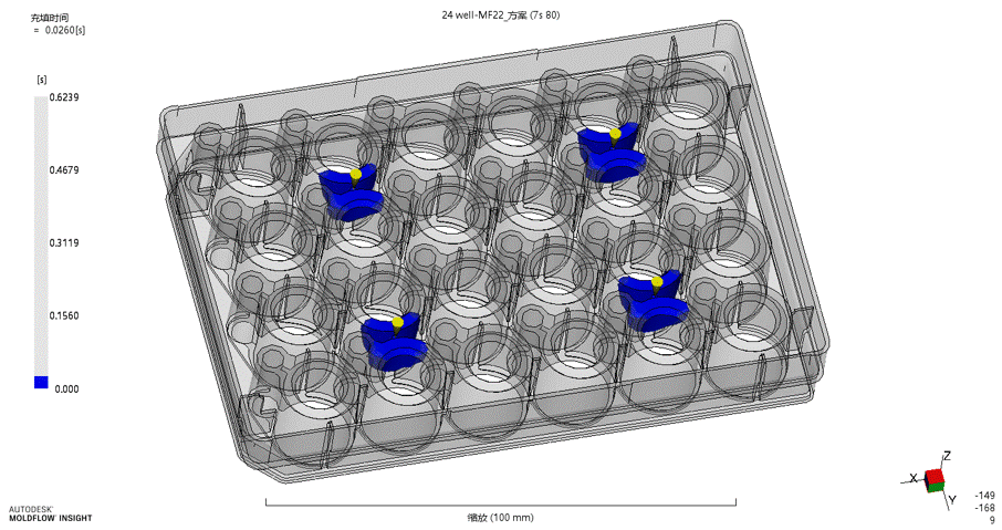
Filling simulation confirming no short shot across the four-point gate layout.
REQUIREMENT
Customer specification
-
Open-bottom 24-well plate requiring thin optical interface compatibility
-
Risk of sink marks from thick wall regions
-
Tight dimensional control for glass bonding alignment
-
Need to ensure uniform filling without short shot
-
Weld lines and air traps expected due to multi-cavity geometry
ENGINEERING APPROACH
DFM output
-
Optimized wall thickness distribution to reduce shrinkage defects
-
Increased draft angles (1.5° → up to 5°) fo reliable demolding
-
Added locating features for glass alignment and assembly
-
Designed four-point gate cold-runner system for uniform filling
-
Verified moldability using Moldflow simulation: no short shot detected, controlled shrinkage (~0.74%), deformation <0.32 mm
AS MANUFACTURED
Production parameters
-
Material: GPPS (SECCO GPPS123 equivalent)
-
Part volume: 53 g
-
Cycle time: ~50 s
-
Mold: three-plate tooling (S136 steel)
-
Machine: 100-ton injection platform
-
Tool lifetime: 100,000 shots
-
Surface finish: Ra ≤ 0.02 µm achievable
-
Gate vestige controlled <0.25 mm
Other programs.
Precision microfluidic chips for single-cell sequencing, direct ELISA and flow cytometry; life-science consumables including 96- and 384-well plates and PCR tubes; over 500 customer projects completed.
Application
\ TESTIMONIALS
“
HiComp has manufactured the injection-molded components of our cartridges for four years, now at millions of units each quarter in their ISO-certified facilities. Consistency at that volume is difficult, and they have delivered it. They stay engaged through every design change.
Dr. Hong Tan
Founder and CEO, ET Healthcare, Palo Alto, California
FAQ


